Raw graphite out of the ground is basically useless to a battery manufacturer. It is full of silica, iron, mica, and sulfur, sized wrong, and shaped wrong. Nobody is putting mine-run flake straight into an anode slurry.
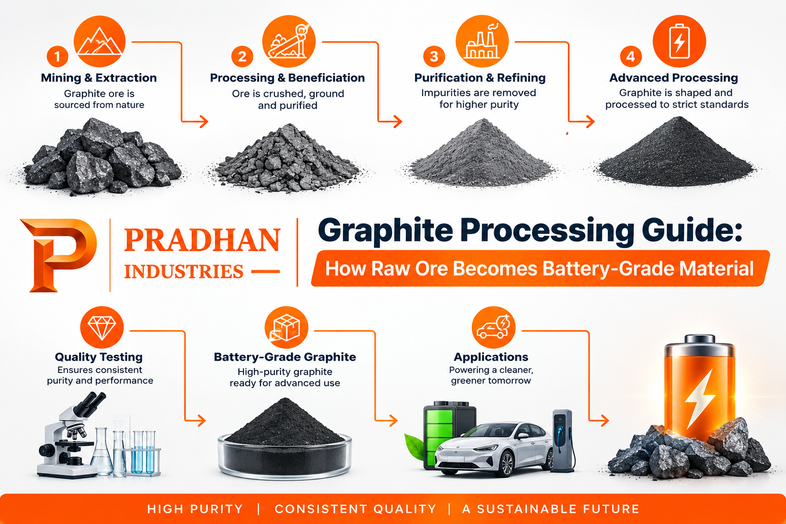
This graphite processing guide walks through the entire industrial chain — from crushing rock at the mine gate to shipping out coated spherical graphite (SPG) at 99.95%+ carbon purity. Four phases, each with its own chemistry, equipment, and failure points.
Graphite beneficiation is the umbrella term for all of this: the mechanical and chemical work that separates graphite from waste rock and upgrades it into something a battery, a refractory, or a lubricant manufacturer can actually use. Get any one phase wrong, and the material downstream either fails performance specs or costs too much to fix later.
Raw Graphite Types & Processing Feeds
Not every processing plant starts with the same input. The feedstock determines which route the material takes:
-
Flake graphite: Found in metamorphic rock, occurs as discrete plates. This is the primary feed for spherical graphite processing because the natural crystal structure survives mechanical shaping.
-
Amorphous graphite: Fine-grained, lower crystallinity, and lower carbon content at the mining stage (often 70–85% C). Routed to lower-spec industrial uses like foundry core washes and refractory coatings, not batteries.
-
Vein (lump) graphite: Rare, extremely high purity at source (sometimes 90%+ C naturally), found primarily in Sri Lanka. Small global supply with niche pricing.
-
Synthetic precursors: Petroleum coke (needle coke preferred) or coal tar pitch. Not “graphite” at the mining stage at all — these are carbon feedstocks converted into graphite through synthetic graphitization at extreme temperatures.
For a battery-grade operation, natural flake graphite is the standard feed. Synthetic graphitization runs on a completely separate track.
Phase 1: Upstream Mineral Beneficiation
This phase concentrates the raw ore, stripping out waste gangue minerals to upgrade the carbon content from a run-of-mine grade (typically 5–15% C) up to 94–96% C flotation concentrate.
Crushing and Grinding
Run-of-mine ore goes through primary and secondary crushing to reduce particle size to roughly 10–20 mm, followed by ball or rod milling. Controlled grinding is critical here: over-grinding destroys large flake sizes, directly reducing market value.
Froth Flotation (Rougher and Cleaner Stages)
Flotation exploits natural hydrophobicity: graphite repels water, while silicate gangue minerals are hydrophilic.
-
The crushed ore is mixed with water and a hydrocarbon collector reagent to coat graphite surfaces.
-
Air bubbles injected into the flotation cell carry hydrophobic graphite to the surface froth layer.
-
The skimmed rougher concentrate (40–60% C) passes through 4 to 8 cleaner flotation cycles to reject remaining silica, mica, and feldspar.
Run-of-Mine Ore (5–15% C)
        │
   Crushing & Milling
        │
  Rougher Flotation (40–60% C)
        │
  Cleaner Flotation Stages (x4–8)
        │
  Flotation Concentrate (94–96% C)
Phase 2: Downstream Spheronization & Micronization
Flotation concentrate particles remain flat flakes. Modern lithium-ion battery anodes require rounded particles to prevent uneven packing and maintain uniform lithium-ion diffusion pathways.
Raw Flake Graphite ──▶ [Micronization: D50 15–20µm] ──▶ [Impact Spheronizer] ──┬──▶ 35–45% Coated SPG Feed
                                                                               └──▶ 55–65% Secondary Fines
-
Micronization: Jet or mechanical mills reduce the concentrate to a target particle size distribution (PSD), targeting a $D_{50}$ of 15–20 microns.
-
Spheronization: High-speed shaping mills repeatedly impact the flakes, folding them into dense, potato-shaped spherical graphite (SPG) with tap densities between 0.9 and 1.1 g/cm³.
-
Yield Dynamics: Roughly 35–45% of mass converts into usable SPG; the remaining 55–65% becomes fine graphite byproduct, which is diverted to conductive additives, lubricants, and foundry recarburizers.
Phase 3: Ultra-High Purification (99.95%+ Carbon)
Battery-grade anode specs require a minimum purity of 99.95% C. Residual metallic and sulfur contaminants cause parasitic side reactions, rapid cell degradation, and internal short-circuit risks.
| Parameter | Chemical Acid Leaching | High-Temperature Thermal | Synthetic Graphitization |
| Operating Temp | 80–120°C | 2,800–3,000°C | 2,800–3,000°C |
| Carbon Purity | 99.95%+ C | 99.95%+ C | 99.90%+ C |
| Reagents / Feed | Hydrofluoric (HF), $H_2SO_4$, $HNO_3$ | Inert atmosphere ($N_2$ / $Ar$) | Petroleum needle coke, pitch |
| Primary Drawback | Hazardous acid handling & wastewater | High electricity consumption | Highest energy input overall |
Chemical (Acid Leaching) Purification
Leaching with hydrofluoric acid (HF) or multi-acid blends dissolves silicates and metal oxides at low energy cost, but requires rigorous chemical containment, scrubber systems, and wastewater neutralization.
Thermal Purification
Thermal processing heats the graphite to 2,800–3,000°C in an inert atmosphere, vaporizing all non-carbon impurities while enhancing lattice crystallinity without hazardous chemical effluents.
Phase 4: Surface Modification & Pitch Coating
Purified SPG surfaces have micro-scale defects that react unpredictably with electrolyte solvents during the first charge cycle.
-
SEI Layer Optimization: Applying a 1–5% amorphous carbon layer via coal tar or petroleum pitch stabilizes the Solid Electrolyte Interphase (SEI), lowering irreversible first-cycle capacity loss.
-
Carbonization: The coated mixture is baked at 900–1,300°C in an oxygen-free furnace to form a continuous carbon shell, improving fast-charging capabilities and cycle life.
Complete Process Flow Summary
| Phase | Input Material | Technology / Method | Target Output & Quality |
| 1. Beneficiation | Run-of-mine ore (5–15% C) | Crushing, milling, froth flotation | Flotation concentrate (94–96% C) |
| 2. Spheronization | Flotation concentrate | Air-jet micronization, mechanical shaping | Unpurified SPG ($D_{50}$ 15–20 µm, 35–45% yield) |
| 3. Purification | Unpurified SPG | Acid leaching (HF) or thermal heating (2,800°C+) | Battery-grade graphite (99.95%+ C) |
| 4. Surface Coating | Purified SPG | Pitch coating & carbonization (900–1,300°C) | Coated SPG (CSPG) ready for anode slurry |
Environmental, ESG & Supply Chain Considerations
-
Tailings Management: Flotation circuits require active closed-loop water recovery to minimize tailings pond footprints.
-
Energy Decarbonization: Thermal purification and synthetic graphitization rely on high electrical inputs; pairing plants with low-carbon hydroelectric or solar grids directly reduces Scope 2 emissions.
-
Supply Chain Diversification: Downstream processing capacity remains concentrated, prompting global cell manufacturers to seek traceable, ESG-compliant regional processing facilities.
Frequently Asked Questions
What is the difference between flake graphite processing and amorphous graphite processing?
Flake graphite retains distinct plate-like crystallinity, allowing it to undergo mechanical spheronization for battery anodes. Amorphous graphite has lower crystallinity and smaller natural particle sizes, making it suited for refractories, metallurgy, and lubricants rather than high-spec battery cells.
Why does spherical graphite processing lose so much material as fines?
Mechanical impact mills round flat flakes by shearing edges and knocking off flake corners. This limits standard SPG mass yields to 35–45%, while the remaining 55–65% fine fraction is collected and sold as industrial carbon additives.
Is acid leaching or thermal purification better for battery-grade graphite?
Both achieve 99.95%+ purity. Chemical leaching offers lower initial capital costs and lower operating temperatures but produces acidic waste streams. Thermal purification eliminates chemical waste at the expense of higher energy consumption.
What temperature is needed for synthetic graphitization?
Synthetic graphitization takes place between 2,800°C and 3,000°C, transforming disordered amorphous petroleum coke or pitch into a crystalline graphite lattice.
Why is pitch coating applied to spherical graphite before battery use?
Pitch coating seals edge defects on the spherical particle surface, forming a uniform amorphous carbon layer that minimizes electrolyte decomposition and stabilizes the SEI layer during early charge cycles.
Graphite processing is an integrated four-stage engineering sequence where yield, purity, and particle geometry must align at each step. Maintaining end-to-end control from run-of-mine ore to final coated SPG ensures consistent anode slurry performance and simplifies supply chain compliance for energy storage markets.